general
| Size |
25 |
| Weight |
Valve with one solenoid |
kg |
20.8 |
| Valve with two solenoids |
kg |
21.1 |
| Valve witch hydraulic actuation |
kg |
20 |
| Switching time adjustment |
kg |
0.8 |
| 3-way pressure reducing valve |
kg |
0.4 |
| Plate for version “T” |
kg |
0.5 |
| Installation position |
|
|
any |
| Ambient temperature ranges (NBR seals) |
|
°C |
-30 … +50 |
| Ambient temperature ranges (FKM seals) |
|
°C |
-20 … +50 |
hydraulic
| Size |
25 |
| Maximum operating pressure |
Port P |
External pilot oil supply |
bar |
315 |
| Internal pilot oil supply (without pressure reducing valve) |
bar |
210 |
| Internal pilot oil supply (with pressure reducing valve) |
bar |
315 |
| Anschluss A |
|
bar |
315 |
| Port B |
|
bar |
315 |
| Port X |
|
bar |
315 |
| Port Y |
|
bar |
315 |
| Port T |
|
bar |
315 |
| Maximum flow |
|
|
l/min |
650 |
| Minimum pilot pressure |
|
|
bar |
12 |
| Maximum pilot pressure |
|
|
bar |
210 |
| Pilot volume for switching process |
|
|
cm³ |
7.7 |
| Hydraulic fluid 1) |
|
|
|
see table |
| Hydraulic fluid temperature range (NBR seals) |
|
|
°C |
-30 … +80 |
| Hydraulic fluid temperature range (FKM seals) |
|
|
°C |
-20 … +80 |
| Viscosity range |
|
|
mm²/s |
2.8 … 500 |
| Maximum admissible degree of contamination of the hydraulic fluid 2) |
|
|
|
Class 20/18/15 according to ISO 4406 (c) |
| Hydraulic fluid |
Classification |
Suitable sealing materials |
Standards |
| Mineral oil |
|
HL, HLP |
NBR, FKM |
DIN 51524 |
| Fast bio-degradable hydraulic fluids |
|
|
|
VDMA 24568 |
| Environmentally compatible |
Insoluble in water |
HETG |
NBR, FKM |
|
| HEES |
FKM |
|
|
Soluble in water |
HEPG |
NBR, FKM |
|
| Other hydraulic fluids on request |
Notices!
Actuation of the manual override is only possible up to a tank pressure of approx. 50 bar. Avoid damage to the bore of the manual override! (Special tool for the operation, separate order, material no. R900024943). When the manual override is blocked, the actuation of the solenoid must be prevented!
The simultaneous actuation of the solenoids must be prevented!
Switching times (= Contacting at the pilot control valve until start of opening of the control edge in the main valve and change in the pressure value by 5 %)
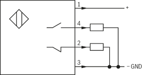
Inductive position switch type QM: electrical connection
The electric connection is realized via a 4-pole mating connector (separate order) with connection thread M12 x 1.
electrical
| Connection voltage (DC voltage) |
V |
24 |
| Voltage tolerance (connection voltage) |
|
+30 %/-15 % |
| Admissible residual ripple |
% |
≤ 10 |
| Max. load capacity |
mA |
400 |
| Switching outputs
|
|
|
|
PNP transistor outputs, load between switching outputs and GND |
| Pinout
|
1 |
|
V |
24 |
| 2, 4 |
Switching output |
mA |
400 |
| 3 |
Earthing (GND) |
V |
0 |